Sunday, May 15, 2011

nerf sentry

My current project is making a NERF sentry gun. It consists of a NERF Vulcan, two servos for the turret, and a webcam.  The gun will need an external battery pack and the trigger modified so  it can be controlled by the Arduino.

I am currently exploring motion tracking with Processing and the JMyron library. Serial communication between Processing and Arduino will be used to send the desired servo positions.


Thursday, April 21, 2011

4 DOF robotic arm

For the final project for ME/EECS 567 we were tasked with applying the principles from lecture into the control of a robot. We chose to design and build a four-link (RRRR) redundant open chain manipulator with a servo contolled gripper as the end effector and implement differential inverse kinematics principles to control the end-effector in the base coordinate frame from velocity inputs.  


Design:

The links were designed in Rhinocerous and laser cut from acrylic according to the design shown below. The piece connecting the links to the base servo was heated and bent into the desired shape. 


The joints are actuated by servos and the controller consists of two joysticks (which allow the user to input a velocity) and a linear soft potentiometer (gripper control). The gripper is composed of a base plate, the two geared arms, a top plate, and a mini servo.  An Arduino Uno microcontroller was used and the servos are powered by an external DC source.

How it works:

The microcontroller reads the joystick positions and maps them to a desired velocity. This desired velocity, along with the right-pseudo inverse* of the Jacobian  is used to calculate the joint angles needed to achieve the desired motion. The right-pseudo inverse of the Jacobian is calculated using the current angles of each joint.To calculate the desired joint velocities, we multiply the Jacobian by the matrix of desired end-effector velocities. We then numerically integrate each joint velocity using Euler’s Method to obtain the desired joint angles for each time step. These values are then written to the servo motorscontrolling the joints.


 *We use the right-pseudo inverse because this is a redundant manipulator, so the Jacobian is not square. 


Results:

Before implementing the physical robot, we first modeled it in MATLAB to verify our mathematical model for the Jacobian was correct and that velocity commands would work as expected. The images below show the final position of our robot after being given commands to move in the x, y, and z directions, respectively. 

X-Velocity Command:


Y-Velocity Command:


Z-Velocity Command:


Gripper test:


 Vertical motion:


Vertical motion and some lateral motion:  


At the end of the video, you can also see the robot approach a singularity and freak out due to the loss of a dimension in the Jacobian.


Monday, November 29, 2010

playing with ferrofluid and electromagnets

The success of our final project for SmartSurfaces was dependent on the control of ferrofluid with homemade electromagnets. Resultantly, a lot of time was spent toying with different possibilities.

enameled wire wrapped (200+ coils) lag bolt: 


ferrofluid "pixels" from coreless electromagnets:

 In the photo above the "pixels" are turned on and off  by the Arduino in response to sound via relays.


unsuccessful attempt to make our own ferrofluid:


working module:

We were required to present a working module of our intended final project which was an array of extended core electromagnets which were turned on in response to changes in light.  Each magnet was paired with a photoresistor and turned on when a shadow was over it.The magnets were made with lag bolts and enameled wire. 

This is a side view of the fully assembled module with the ferrofluid in it. The spikes are the threads of the lag bolts which were used as the core of the electromagnets.


A spiral of ferrofluid formed by turning on one of the electromagnets:


VIDEO GOES HERE


Tuesday, October 19, 2010

solar tracker

One of the projects for a course I took fall semester was a solar tracker. The course was based around biomimetic smart surfaces so this solar tracker was an attempt to emulate the human eye. The biomimicry aspect of this project comes from how the solar tracker receives the signal to move. Similar to an eye, the light comes through a pinhole and contacts the sensor array (5 photoresistors). The light intensity is then read as a number and the device responds by moving towards it. 


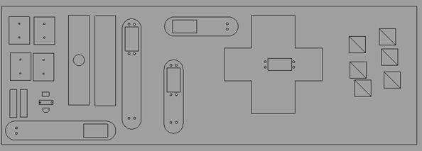
The device consists of a sphere (the eye) fixed at two points to a turntable so it can rotate freely. An arc of pegs ( which was coined 'the mohawk') is attached to the bottom of the sphere and meshes with a gear (powered by a servo) that rotates the eye. The sphere was made by routing a MDF hemisphere and vacuum forming two pieces. The mohawk and the base of the tracker were laser cut from acrylic.


routing the mold:


sphere with mohawk partially attached:


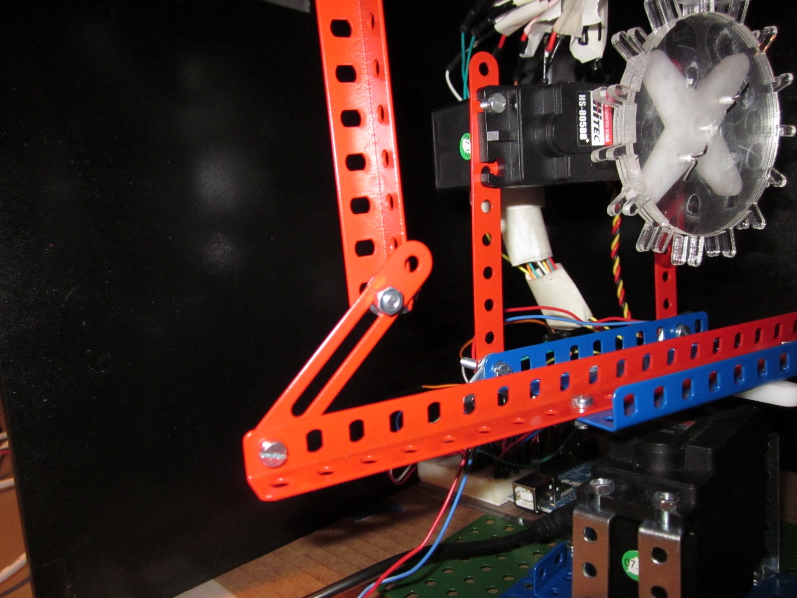
The gear/mohawk mechanism is then attached to another servo that allows the whole eye to rotate on the xy plane by moving  the turntable. The  image below is a photograph of one of the joints connecting the turntable and the xy plane servo and the servo which contacts the mohawk. 


VIDEO GOES HERE


This is an image of our fully functional two-axis solar tracking device. When the pin hole has oriented with a light source, the green led indicator light comes on and is visible through the front of the acrylic case. 


This is the code used for operating the servos to track a light source:


#include <Servo.h>

Servo zyplane; //servo attached to the base servo rotates on the zy plane (around x axis)
Servo xyplane; 
int pos = 90;
int pos2 = 90;

//PhotoResistors (these are all analog pins)
int photo1 = 0; 
int photo2 = 1;
int photo3 = 2;
int photo4 = 3;
int photo5 = 4;

//alignment indicator LED (this is a digital PWM pin)
int ledPin = 5;  

void setup()
{
  pinMode(ledPin, OUTPUT); //sets the led pin to output
  pinMode(photo1, INPUT);
  pinMode(photo2, INPUT);
  pinMode(photo3, INPUT);
  pinMode(photo4, INPUT);
  pinMode(photo5, INPUT);

  zyplane.attach(10);// attach the pin 10 servo to servo object
  xyplane.attach(9);
  Serial.begin(9600); // use the serial port
}

void loop()
{
 //--------------------gives a value for each photoresistor------------------------------
 int light1 = analogRead(photo1); //Read the lightlevel

 int light2 = analogRead(photo2); //Read the lightlevel

 int light3 = analogRead(photo3); //Read the lightlevel

 int light4 = analogRead(photo4); //Read the lightlevel

 int light5 = analogRead(photo5); //Read the lightlevel


//----------------------------------operates xyplane servo---------------------------------//

  if (light1>light3 && light1>light5  && light1>light4  && light1>light2 && pos!=180 ){
      xyplane.write(pos);
  delay(100);
  pos ++;
  }
    
  if (light3>light1 && light3>light5  && light3>light4  && light3>light2 && pos!= 0  ){
      xyplane.write(pos);
  delay(100);
  pos --;
}
//-------------------------------operates zyplane servo----------------------------------------
   //zyplane.attach(10);// attach the pin 10 servo to servo object
  
  if (light2>light4 && light2>light5  && light2>light3  && light2>light1 && pos2!=180 ){ 
  zyplane.write(pos2);
  delay(100);
  pos2 --;
  }
  
  if(light4>light2 && light4>light5  && light4>light1  && light4>light3 && pos2 != 0){
  zyplane.write(pos2); //goes to the position
  delay(100); //this gives the servo time to move
  pos2 ++;
}


//---------------------------operates LED alignment indicator--------------------------------------

 if (light5>light1 && light5>light2 && light5>light3 && light5>light4){

  digitalWrite(ledPin, HIGH);
 }
  else{ 
    digitalWrite(ledPin, LOW);
    
  }