My current project is making a NERF sentry gun. It consists of a NERF Vulcan, two servos for the turret, and a webcam. The gun will need an external battery pack and the trigger modified so it can be controlled by the Arduino.
I am currently exploring motion tracking with Processing and the JMyron library. Serial communication between Processing and Arduino will be used to send the desired servo positions.
For the final project for ME/EECS 567 we were tasked with applying the principles from lecture into the control of a robot. We chose to design and build a four-link (RRRR) redundant open chain manipulator with a servo contolled gripper as the end effector and implement differential inverse kinematics principles to control the end-effector in the base coordinate frame from velocity inputs.
Design:
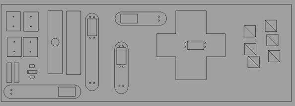
The links were designed in Rhinocerous and laser cut from acrylic according to the design shown below. The piece connecting the links to the base servo was heated and bent into the desired shape.
The joints are actuated by servos and the controller consists of two joysticks (which allow the user to input a velocity) and a linear soft potentiometer (gripper control). The gripper is composed of a base plate, the two geared arms, a top plate, and a mini servo. An Arduino Uno microcontroller was used and the servos are powered by an external DC source.
How it works:
The microcontroller reads the joystick positions and maps them to a desired velocity. This desired velocity, along with the right-pseudo inverse* of the Jacobian is used to calculate the joint angles needed to achieve the desired motion. The right-pseudo inverse of the Jacobian is calculated using the current angles of each joint.To calculate the desired joint velocities, we multiply the Jacobian by the matrix of desired end-effector velocities. We then numerically integrate each joint velocity using Euler’s Method to obtain the desired joint angles for each time step. These values are then written to the servo motorscontrolling the joints.
*We use the right-pseudo inverse because this is a redundant manipulator, so the Jacobian is not square.
Results:
Before implementing the physical robot, we first modeled it in MATLAB to verify our mathematical model for the Jacobian was correct and that velocity commands would work as expected. The images below show the final position of our robot after being given commands to move in the x, y, and z directions, respectively.
X-Velocity Command:
Y-Velocity Command:
Z-Velocity Command:
Gripper test:
Vertical motion:
Vertical motion and some lateral motion:
At the end of the video, you can also see the robot approach a singularity and freak out due to the loss of a dimension in the Jacobian.